me being who i am, can never leave well enough alone.
while the kit supplied headers in the 66 nova kit look “ok” i feel i have to try to make them better.
i always preferred the look of big bore coated headers

out to the garage to grab some solder of the appropriate diameter

i want 8 lengths of this, i snip them off with a pair of cutters, problem is they come off a bit bent.

secret to getting them straight again lies in 2 pieces of wood. set one block on the table, set a piece of solder on it, cover with the other block of wood and move it back and forth.

when you are done rolling it, the piece will be straight.

do this with all 8 pieces

now i have seen people bend up headers right on the actual engine before, i prefer not to do that. i grab a piece of wood to use as a buck or a template.

use the kit supplied headers as a guide and drill 4 holes just big enough to hold the pieces of solder. make them close, exact is not required for this step
insert 4 of the pieces of solder into the holes

starting with the lowest rear tube, start forming them into the correct position

i normally use a small jewelers screwdriver as a helper when bending headers, when you need a bend you can either lay it flat and curve over it or put the tip in the wood and bend around it

tweak and bend until you get the shape you want.


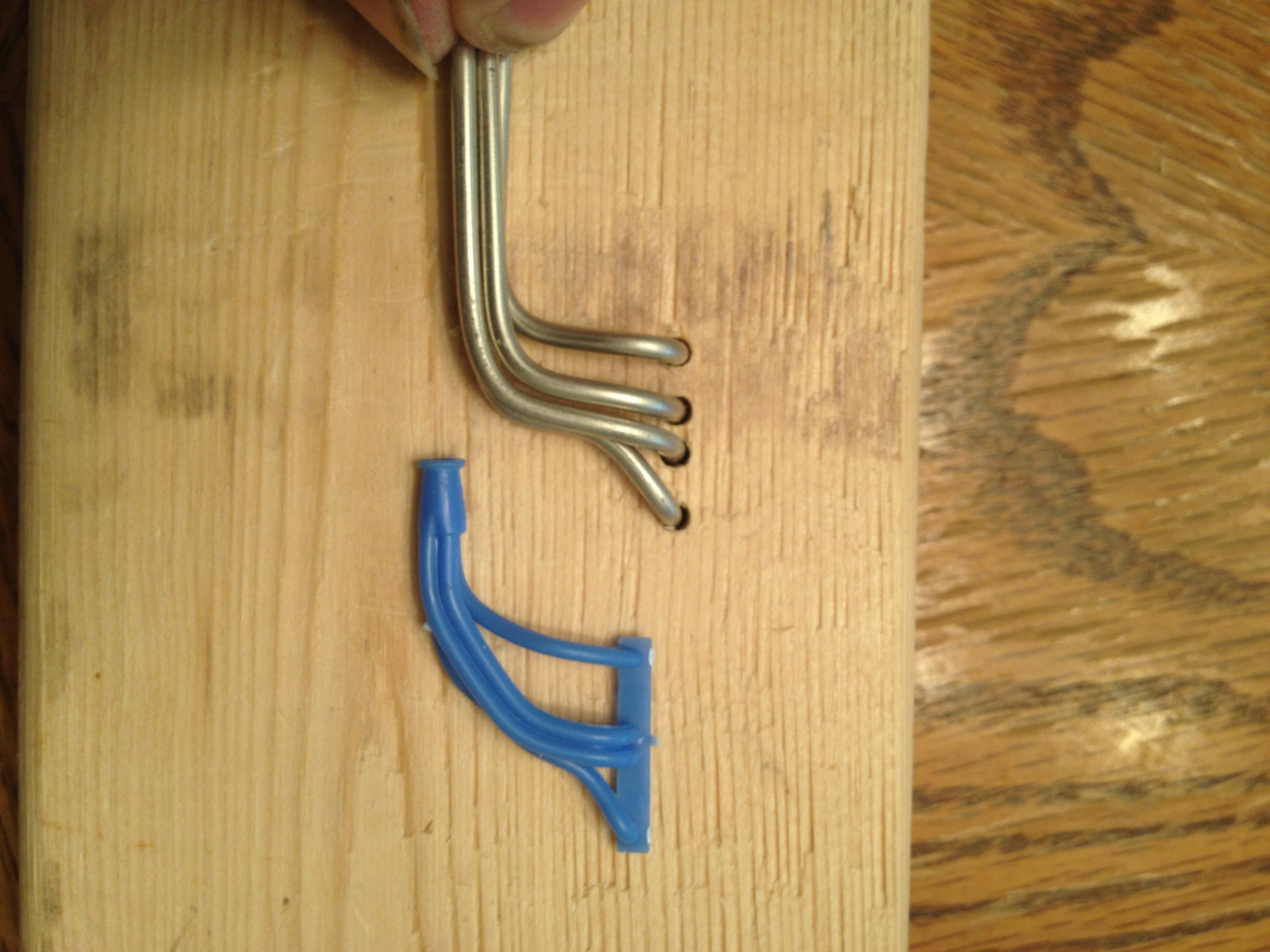
this puts me close on the right side, so out comes the superglue

put a drop around where the collectors will be and let it set up
now you have one side with extended front and rear tubes

keep it in the template just for ease of holding it still. with a saw or knife trim the collector side of the tubes down to size.

remove from the template and cut the mounting side slightly longer than flush ( these will push into holes in the head when it is time to install.
repeat process for other side.

when done you should end up with something like this

headers are now in a basic raw form and shape,

now to add collectors and drill holes in the block to accept them.
grab a piece of heat shrink tubing ( electrical store item) that just covers the end of the headers, cut 2 pieces about 1/2 inch long. length really doesnt matter at this time, what does matter is that your cuts are straight.


slide the heat shrink over the headers on the collector side so about 1/4 inch is covering the end of the headers
than grab our friend the portable heat source =o)

slowly heat the heat shrink tubing till it closes in on the headers and created the “collector”

at this time the collector ends are too long for my liking, trim then back with a sharp hobby blade to a length that suits you.

now it is time to sort out where these will fit on our engine.
grab a drill bit the same size as your solder headers

carefully drill out your cylinder heads in the correct locations

patiently test fit your headers onto the block by sliding each tube into each hole on the engine ( these will get detail master header flanges installed before final assembly but you could also ” fake” flanges with paint )


being made of solder, the headers are somewhat flexible if you are careful, originally these were a bit too wide so i simply squeezed them a bit to where i needed them.
before final assembly i will have to notch the frame slightly for a little bit of clearance but that is because the tube diameter is a bit bigger than the kit supplied versions.

cya next time
